
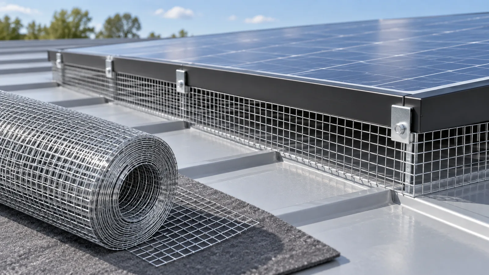
Bird activity around a rooftop solar array is a site problem with a very specific geometry: the space between the outer module edge and the roof. A perimeter mesh skirt may be considered where an installer wants to limit access beneath the array while retaining the designed clearance and maintenance route. The useful purchase unit is not simply “one roll of bird mesh.” Buyers need a measured perimeter, a defined mesh construction and an attachment plan agreed with the photovoltaic installation team.
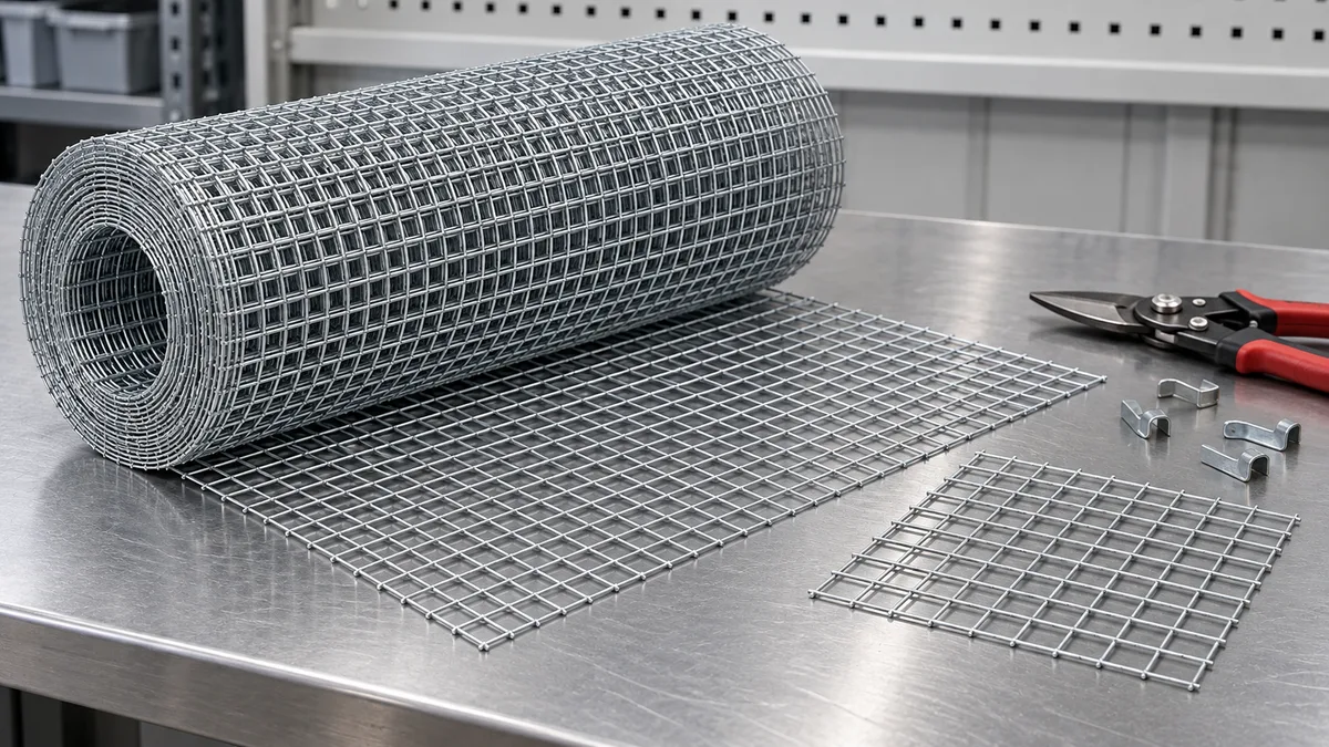
Our galvanized small-aperture welded wire mesh is the product reference for this guide. The reference image shows a silver roll with straight wires crossing at right angles to form small square openings. The wire intersections are welded. It is not a hexagonal twisted net or a chain-link fabric. Final dimensions, coating specification and suitability for a particular array must be agreed in the order.
Survey the array before choosing a roll width
Walk the permitted access route with the solar installer and make a plan of the outer array perimeter. Measure each exposed run separately. Record changes in the gap between module frame and roof covering, including at corners, roof ridges, equipment penetrations and changes of roof pitch. A single measurement at the front edge will not necessarily describe the side edges or an array built on rails above an uneven surface.
On the drawing, distinguish the length of mesh required around the edge from the height of the mesh strip. Allow for the installer-approved overlap and fastening detail at joints. Mark locations that need a separate shaped piece rather than stretching or folding the roll over a large gap. The survey should also identify safe places to reach the work and any system components that must remain accessible.
Photovoltaic module frames, mounting rails and roof coverings vary. Ask the installer or system owner to confirm the permitted attachment points and the system maker's instructions before any mesh is ordered for installation. A buyer should not assume that drilling a frame, attaching to a roof membrane or routing wire over electrical components is acceptable.
Specify the square opening and wire separately
For welded mesh, give the opening as a measured clear opening or as the agreed centre-to-centre pitch, and identify which convention the figures use. Add the wire diameter and the intended roll width and length. If an installer has an exclusion requirement for a particular animal, have that team approve the opening and the complete edge detail. A small opening in the middle of a roll cannot compensate for a wide unclosed gap at its ends.
Confirm whether the ordered material is galvanized after welding, made from pre-galvanized wire or supplied to another coating specification. Those routes are not interchangeable simply because the product looks silver. Include any corrosion or coating requirement supported by the project specification and ask for the corresponding documentation if needed. Avoid treating a product photograph as a test report or a service-life guarantee.
Request a sample that shows several full openings and a cut edge. Check whether the wires and welds are consistent and whether the strip can be shaped to the measured perimeter using the proposed fabrication method. If the job requires a dark or polymer-coated finish for appearance or environmental reasons, request that as a separate confirmed option; the referenced roll is shown in a natural silver galvanized finish.
Plan the lower edge, corners and joints
A neat top attachment is only half the perimeter detail. The lower edge should meet the roof or an approved support in the way the installer has designed. Account for standing seams, corrugations, tiles, raised flashing and drainage paths. The goal is a continuous detail around the array, not a decorative strip with large unplanned openings at the bottom.
Identify outside and inside corners on the layout. Specify whether the installer will bend one continuous strip, overlap two pieces or use a shaped panel. The finished edge should avoid loose cut wires where they could contact cables, roofing or a maintenance worker. State who is responsible for deburring, trimming and closing exposed ends.
Joint position matters when ordering rolls. A long straight run may use continuous material, while short returns can create more offcuts. Provide the run schedule and quantities rather than ordering on perimeter length alone. Allow for agreed overlaps, shaped pieces and reasonable cutting waste in the bill of materials; have the installer verify the take-off.
Keep ventilation, drainage and service access in the plan
Solar arrays are installed with a designed space beneath their modules. The mesh arrangement must be reviewed with the system installer so that it does not conflict with the manufacturer's ventilation requirements, cable management, mounting hardware or applicable fire and access provisions. The presence of openings in the mesh does not by itself prove that the final assembly meets those requirements.
Show the locations of any equipment requiring access beneath or beside the modules. The installer can then define a removable or serviceable section and an appropriate fastening method. The owner should understand how that section is opened and refitted during routine maintenance. Avoid a continuous perimeter detail that can only be removed by cutting the whole strip.
Before fitting a skirt around an existing array, the site team should inspect the cavity and follow its approved procedure for cleaning or removing existing nesting material. Closing an occupied or obstructed space without that review can make maintenance harder. After installation, include the mesh and its fixings in routine visual inspections, along with the array and roof condition.
What to send for a useful quotation
If you are comparing welded-mesh constructions more generally, our welded wire mesh specification guide explains the difference between opening, wire diameter, finished size and edge condition. For a solar array, add the measured roof and module interface to those product details.
- Array layout with separate exposed perimeter runs, corners and access sections.
- Measured gap range from module or approved support to roof along each run.
- Required clear opening or pitch, wire diameter, galvanized coating specification and roll width.
- Installer-approved fixing and lower-edge arrangement, with any separate clips or fasteners identified.
- Cut-edge and joint treatment, quantity take-off, sample and documentation requirements.
- Packing preference, shipping destination and the party responsible for on-site installation.
Send the drawing and mesh specification through our contact page. We can review the requested welded mesh format and supply scope for quotation. The solar installer should approve the final attachment and site-specific installation method before fitting any perimeter barrier.